Thin Films Series: The Invisible Shield Inside Every Jet Engine
From the roar of a jet engine propelling an aircraft across continents to the steady hum of a gas turbine generating electricity for our cities, we are surrounded by feats of immense power. These machines operate at the very edge of material science, harnessing controlled explosions and extreme temperatures to create motion and energy. But their remarkable performance and reliability depend on an often-overlooked technology, a layer of engineered material so thin it is measured in microns, yet so critical it allows metal components to survive in environments hotter than their own melting point. This is the world of Thermal Barrier Coatings (TBCs).
This article, the first in a series on advanced manufacturing, delves into the science, application, and critical importance of these sophisticated thin films. We will explore how they work, why they are essential for modern aviation and power generation, and how a complex global ecosystem works to produce and maintain them.
The Soaring Demand for Power and Efficiency
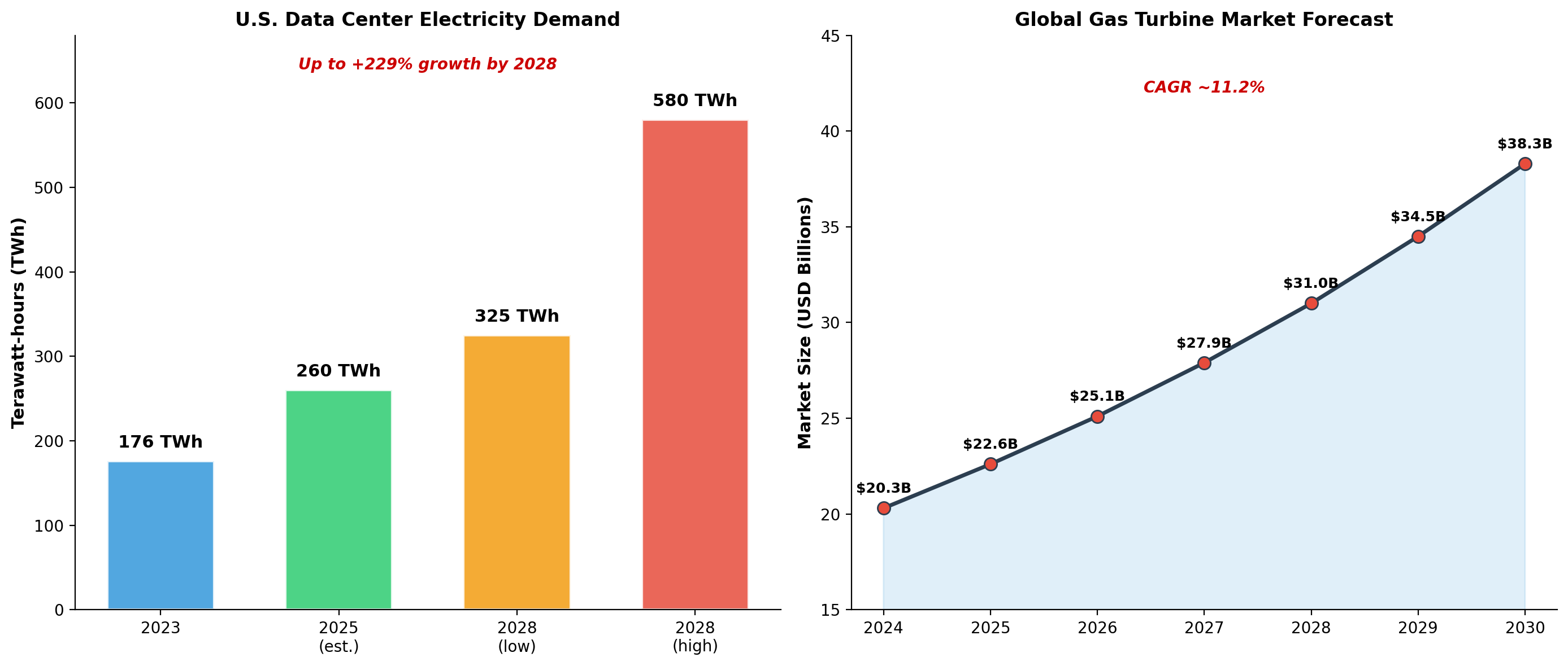
The relentless drive for greater efficiency is a constant in engineering. In aviation, it means lower fuel burn, reduced emissions, and longer range. In power generation, it means producing more electricity from the same amount of fuel. This drive, coupled with global economic growth, has led to a robust and expanding market for gas turbines. The global gas turbine market, valued at over $22 billion in 2025, is projected to grow at a compound annual growth rate (CAGR) of over 11% for the next decade [1].
More surprisingly, a new and voracious consumer of energy is supercharging this demand: the digital economy. The proliferation of data centers and the rise of artificial intelligence are creating an unprecedented need for reliable, large-scale power. U.S. data center electricity consumption alone is projected to grow from 176 terawatt-hours (TWh) in 2023 to as high as 580 TWh by 2028—a staggering increase of up to 229% [2]. To meet this demand, utilities are increasingly turning to natural gas turbines as a key source of near-term power generation [3].
The Temperature Problem: A Widening Gap
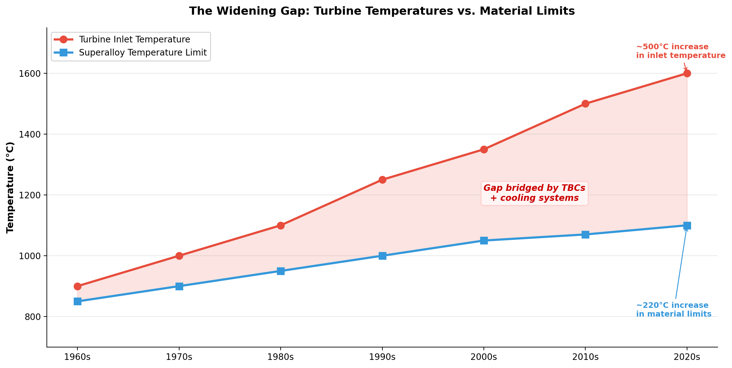
To achieve higher efficiency, turbines must run hotter. This fundamental thermodynamic principle has led to a continuous rise in turbine inlet temperatures, which now routinely exceed 1500°C (2732°F) [4]. However, the nickel-based superalloys that form the structural core of turbine components have not been able to keep pace. Over the past several decades, while turbine inlet temperatures have increased by approximately 500°C, the thermal tolerance of the underlying alloys has only improved by about 220°C [4].
This creates a significant thermal gap. How can a machine operate reliably when its internal environment is hundreds of degrees hotter than the melting point of its own components? The answer lies in a sophisticated system of internal cooling and, crucially, the application of Thermal Barrier Coatings.
The Solution: A Multi-Layered Thermal Shield
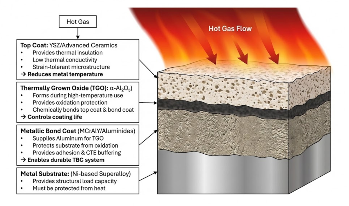
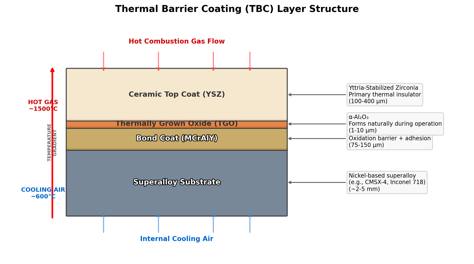
A TBC is not a single material, but a complex, multi-layer system, typically 100 µm to 2 mm thick, engineered to create a steep thermal gradient. It insulates the structural metal, keeping it at a safe operating temperature while the outer surface is exposed to the extreme heat of the gas path. A typical TBC system consists of four primary layers:
- The Superalloy Substrate: The load-bearing component itself, typically a nickel-based superalloy chosen for its high-temperature strength and creep resistance.
- The Metallic Bond Coat: A dense, metallic layer (often a NiCrAlY or NiCoCrAlY alloy) that provides a crucial link between the metal substrate and the ceramic top coat. It also serves as a reservoir of aluminum.
- The Thermally Grown Oxide (TGO): An extremely thin layer of aluminum oxide (α-Al₂O₃) that forms on the surface of the bond coat at high temperatures. This layer is the true bonding interface for the ceramic and is critical to the coating's longevity.
- The Ceramic Top Coat: The outermost layer and the primary insulator. It is most commonly made of Yttria-Stabilized Zirconia (YSZ), a ceramic material with very low thermal conductivity that remains stable at extremely high temperatures.
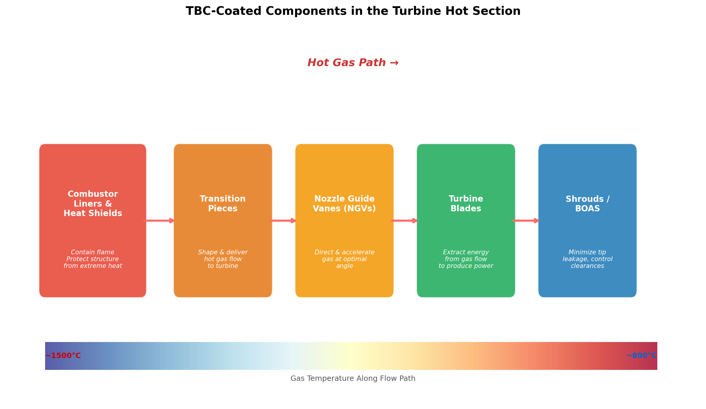
These coatings are applied to the most thermally-exposed components in the turbine's "hot section," including the combustor liners, transition pieces, nozzle guide vanes, and the turbine blades themselves.
How TBCs are Made: A Tale of Two Processes
The application method of the ceramic top coat is critical to its performance and durability. Two methods dominate the industry: Air Plasma Spray (APS) and Electron Beam Physical Vapor Deposition (EB-PVD).
- Air Plasma Spray (APS): In this process, YSZ powder is injected into a high-temperature plasma jet, which melts the powder and propels it onto the component's surface. The molten droplets rapidly solidify, creating a microstructure of overlapping "splats." This structure contains a network of pores and microcracks that give it excellent thermal insulating properties and some tolerance to thermal expansion. APS is a versatile and cost-effective method, often used for static components like combustors and vanes.
- Electron Beam Physical Vapor Deposition (EB-PVD): This is a more advanced, vacuum-based process. A high-energy electron beam is used to melt and evaporate a solid ingot of YSZ material. The vapor then travels in a straight line and condenses on the component's surface, growing into a unique structure of vertically-aligned, feather-like columns. This columnar structure provides outstanding strain tolerance, making it highly resistant to the stresses of thermal expansion and contraction. For this reason, EB-PVD is the preferred method for rotating components like turbine blades, which experience the highest mechanical and thermal stresses.
The Enemy Within: Why TBCs Fail
Despite their sophistication, TBCs have a finite lifespan and are a life-limiting factor for the components they protect. Their failure is a complex process that is still the subject of intense research, but it is often driven by the behavior of the ultra-thin TGO layer. The growth of this oxide layer, while essential for bonding, also introduces stress at the interface between the metallic bond coat and the ceramic top coat. Over many cycles of heating and cooling, these stresses can lead to crack formation and, eventually, the spallation (flaking off) of the ceramic top coat, which is a catastrophic failure mode [5].
Other factors contributing to failure include:
- Thermal Shock: The rapid temperature changes during engine start-up and shutdown create immense stress.
- Sintering: At very high temperatures, the ceramic top coat can slowly become denser, which reduces its strain tolerance and can lead to cracking.
- Hot Corrosion and CMAS Attack: Impurities in the fuel or ingested sand and dust can form molten deposits (known as Calcia-Magnesia-Alumina-Silica, or CMAS) that can infiltrate and degrade the porous ceramic top coat.
The Inspection Challenge: Seeing the Unseen
Because TBC failure can have catastrophic consequences, rigorous inspection is a critical part of both manufacturing and maintenance. However, inspecting these multi-layered coatings on complex, 3D components is incredibly challenging. The most critical failure mechanisms occur at the buried interfaces, hidden from view.
Manufacturers and MRO providers rely on a suite of Non-Destructive Testing (NDT) methods, but each has its limitations:
| Method | Primary Capability | Key Limitation |
|---|---|---|
| Visual (10-40×) | Surface cracks, spallation | No subsurface visibility |
| Eddy Current | Metallic layer thickness | Calibration-sensitive |
| Ultrasonic | Gross thickness, delamination | Poor resolution in porous ceramics |
| Optical / Laser | Surface geometry | Surface-only, line-of-sight |
| IR Thermography | Large-area delamination | Limited depth sensitivity |
| FPI | Surface-connected cracks | No coating insight |
| Metallography | True layer structure | Destructive, limited sampling |
| SEM / EDS | Chemistry, oxide analysis | Localized, destructive |
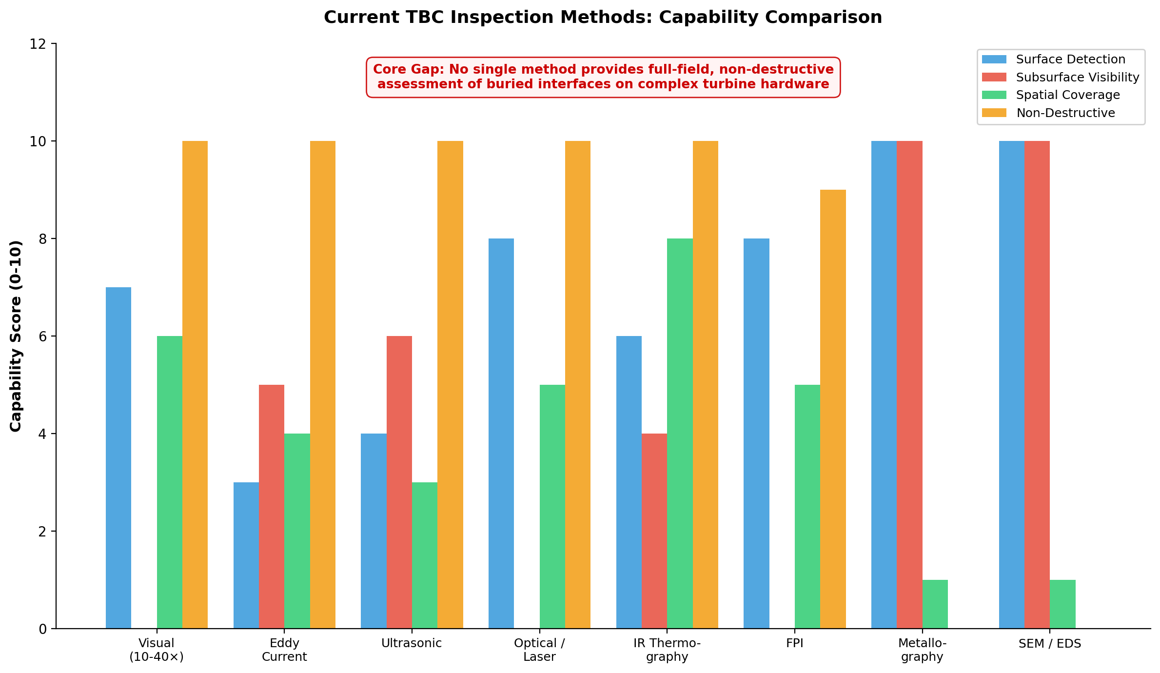
This patchwork of techniques means that coating acceptance decisions are often based on an incomplete picture of the coating's true condition. This uncertainty forces the industry to adopt conservative safety margins, leading to higher strip-and-recoat rates during maintenance and increased scrap risk in production.
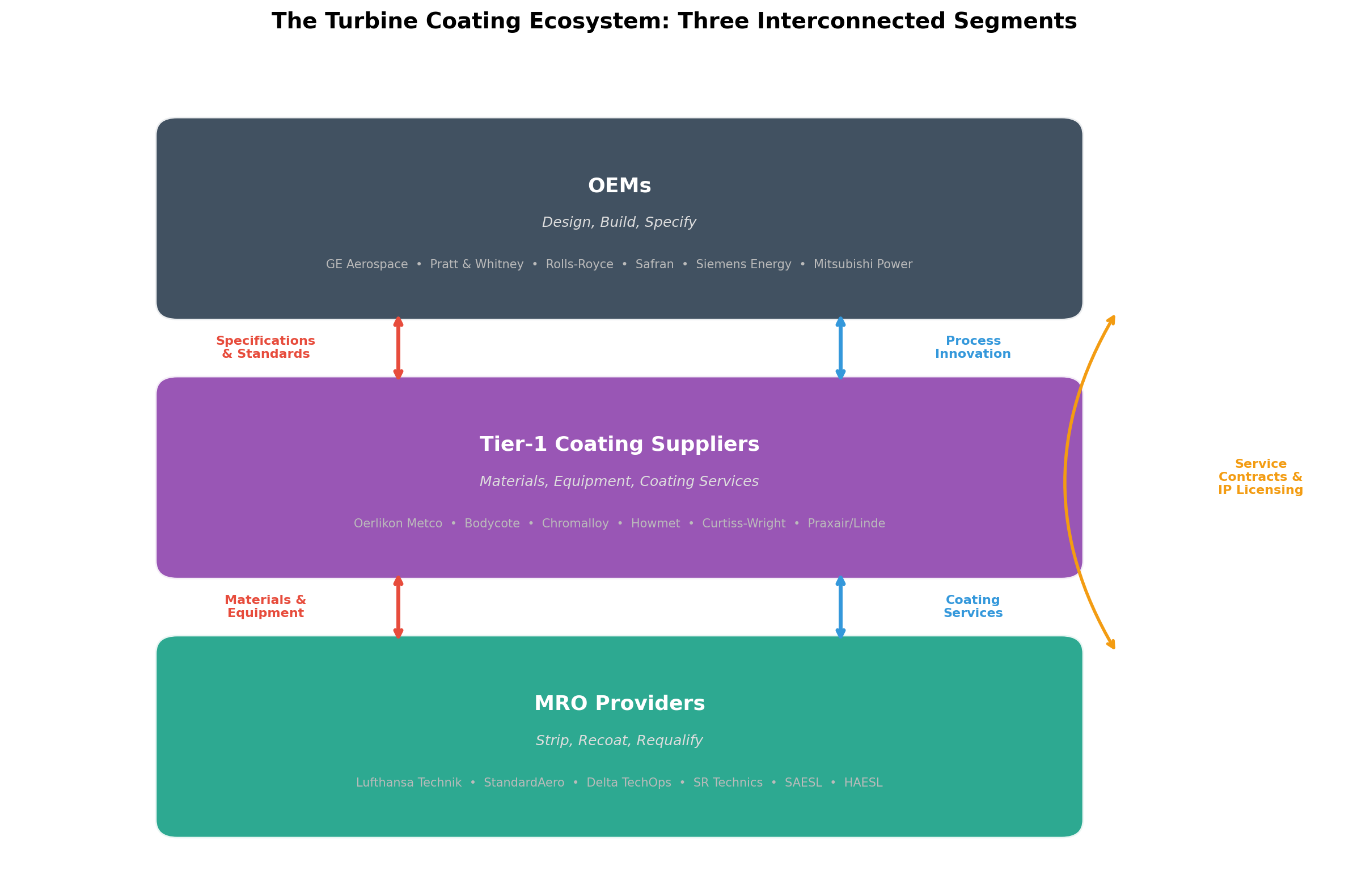
A Complex Global Ecosystem
The production and maintenance of TBCs is a global enterprise involving three key segments:
- Original Equipment Manufacturers (OEMs): Companies that design and build the turbines. They define the material specifications, coating designs, and acceptance standards for the entire supply chain.
- Tier-1 Coating Suppliers: Specialized companies that provide the coating materials, application equipment, and often perform the coating services themselves.
- Maintenance, Repair, and Overhaul (MRO) Providers: A network of airline-owned, independent, and OEM-affiliated shops that service the engines throughout their operational life. The MRO market for aircraft engines alone is a massive, ~$63 billion industry [6].
These segments are deeply interconnected. OEMs push standards down to their suppliers, while Tier-1s develop new process innovations that they license up to the OEMs. MROs, in turn, are major consumers of coating materials and services, often applying more coatings to a single component over its lifetime than the original manufacturer.
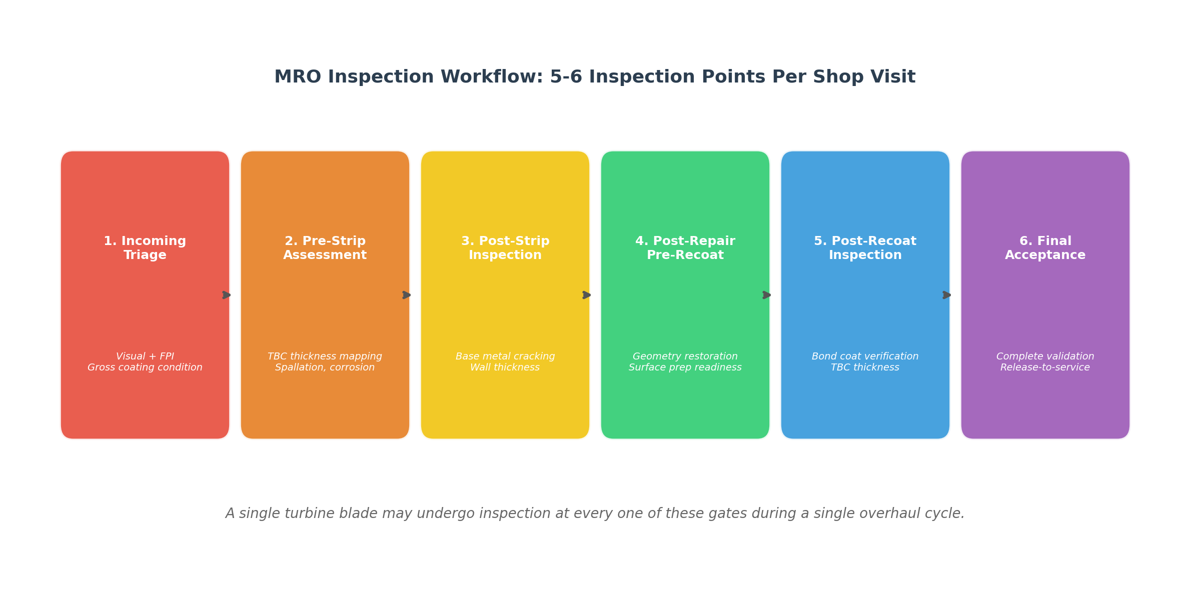
During a single MRO shop visit, a high-pressure turbine blade might be inspected up to six times: upon arrival, after stripping, after base metal repair, pre-recoat, post-recoat, and for final acceptance. This high inspection density underscores the critical role of coatings in the service and economics of the entire industry.
The Future: Pushing the Boundaries Even Further
The quest for higher efficiency is far from over. The next generation of turbine engines will push temperatures and pressures even higher, requiring new material systems. Ceramic Matrix Composites (CMCs) are a revolutionary class of material that are much lighter and can withstand higher temperatures than even the most advanced superalloys. CMCs, however, require their own unique protective coatings, known as Environmental Barrier Coatings (EBCs), to protect them from the water vapor present in the combustion environment [7].
The development of these new coating systems, along with advanced, full-coverage inspection technologies, will be the key enablers for the next leap in aviation and power generation efficiency.
Conclusion
Thermal Barrier Coatings are a powerful example of how innovation at the microscopic level can enable performance at a massive scale. They are a critical, high-leverage technology that underpins the safety, efficiency, and economic viability of modern aviation and power generation. As we push for a more sustainable and efficient future, the role of these unseen, ultra-thin films will only continue to grow in importance.
References
[1] Global Market Insights. "Gas Turbine Market Size, Growth Outlook 2026-2035." Accessed February 10, 2026. https://www.gminsights.com/industry-analysis/gas-turbine-market
[2] Yañez-Barnuevo, Miguel. "Data Center Buildout Is Hungry for Fossil Fuels." Environmental and Energy Study Institute, January 26, 2026. https://www.eesi.org/articles/view/data-center-buildout-is-hungry-for-fossil-fuels
[3] Martos, Jenny. "Betting big on data centers, U.S. now leads world for new gas power development." Global Energy Monitor, January 2026. https://globalenergymonitor.org/report/betting-big-on-data-centers-u-s-now-leads-world-for-new-gas-power-development/
[4] Oerlikon Metco. "Understanding Thermal Barrier Coatings (TBCs)." Accessed February 10, 2026. https://www.oerlikon.com/metco/en/products-services/materials/understanding-tbcs-thermal-barrier-coatings/
[5] "Thermal barrier coating." Wikipedia. Accessed February 10, 2026. https://en.wikipedia.org/wiki/Thermal_barrier_coating
[6] Counterpoint Market Intelligence. "Aero-Engine Maintenance, Repair and Overhaul 2025." Accessed February 10, 2026. https://counterpoint.aero/product/aero-engine-maintenance-repair-and-overhaul/
[7] NASA. "Environmental Barrier Coatings for Ceramic Matrix Composites." NASA Technology Transfer Program. Accessed February 10, 2026. https://technology.nasa.gov/patent/lew-tops-136
Written by Bogdan Cristei and Manus AI